
06 July 2009
01 April 2008
April Fool's Tuesday
The spring has not really come here yet, but I felt it was the time to work a couple of English stations across the North Sea again.

The conditions were average and the five stations worked are well known, regular participants.

The conditions were average and the five stations worked are well known, regular participants.
02 October 2007
October VHF Tuesday
I've been too busy with other things recently to do any work on antennas, radio or the blog. Today was a good oportunity to dust off the VHF yagi and try some QSOs across the North Sea.
I had 8 contacts into 5 squares during the first hour, ODX being G4DBL (389 km):
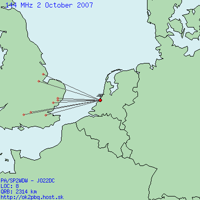
The conditions were good in the beginning, then quite unstable. In the second hour of the contest I didn't hear much and there was little point in extending the time spent at the radio. 8 QSOs is a definitive improvement over my previous results.
I had 8 contacts into 5 squares during the first hour, ODX being G4DBL (389 km):
The conditions were good in the beginning, then quite unstable. In the second hour of the contest I didn't hear much and there was little point in extending the time spent at the radio. 8 QSOs is a definitive improvement over my previous results.
04 September 2007
September VHF Activity Tuesday
Another VHF activity Tuesday.
My impression was that the propagation conditions were rather bad and the level of activity quite low. Maybe some "big guns" have not yet recovered after the IARU contest last weekend?
Despite the weak signals I managed 4 QSOs with:
G4IRC/p (210 km)
G4DHF (321 km)
G0AFH (282 km)
G4DEZ (311 km)

I also copied M0BRA and G3MEH, but didn't succeed in being heard.
My impression was that the propagation conditions were rather bad and the level of activity quite low. Maybe some "big guns" have not yet recovered after the IARU contest last weekend?
Despite the weak signals I managed 4 QSOs with:
G4IRC/p (210 km)
G4DHF (321 km)
G0AFH (282 km)
G4DEZ (311 km)

I also copied M0BRA and G3MEH, but didn't succeed in being heard.
02 September 2007
IARU VHF Contest 144 MHz
The IARU VHF Contest is probably the most important regular event on 144 MHz in Europe. I thought it would be a good opportunity to test the new 5-element yagi and to have some QSOs, since the level of activity during this contest is usually hard to beat at any other time.
I operated one hour on Saturday evening and one hour on Sunday afternoon (the last hour of the contest). I managed to contact 13 stations overall (3 from Germany, 3 from the Netherlands and 7 from England).
The propagation conditions to Britain seemed very good - some stations were even peaking S9 on the S-meter! (on my indoor antenna). I had no difficulty being heard on the other side of the North Sea.
Working with Dutch and German stations was a bit more difficult, even though the distances did not exceed 300 km in that direction.

Having seen reports on dx-cluster I realized there was a tropo to France and Spain during the contest. However, this direction is completely closed for me from my fist-floor appartment.
In summary, I'm happy with the results of these two hours spent at the radio. They confirmed that the antenna works good and that it is possible to take part in a VHF conetst from a space-limited, indoors location. At the same time one can't expect miracles from such a setup.
I operated one hour on Saturday evening and one hour on Sunday afternoon (the last hour of the contest). I managed to contact 13 stations overall (3 from Germany, 3 from the Netherlands and 7 from England).
The propagation conditions to Britain seemed very good - some stations were even peaking S9 on the S-meter! (on my indoor antenna). I had no difficulty being heard on the other side of the North Sea.
Working with Dutch and German stations was a bit more difficult, even though the distances did not exceed 300 km in that direction.

Having seen reports on dx-cluster I realized there was a tropo to France and Spain during the contest. However, this direction is completely closed for me from my fist-floor appartment.
In summary, I'm happy with the results of these two hours spent at the radio. They confirmed that the antenna works good and that it is possible to take part in a VHF conetst from a space-limited, indoors location. At the same time one can't expect miracles from such a setup.
16 August 2007
New VHF antenna (5-element yagi)
I decided to use the full available length of the 2-metre wooden boom to build a 5-element yagi. Having played a bit with 4nec2 I ended up with the following design:
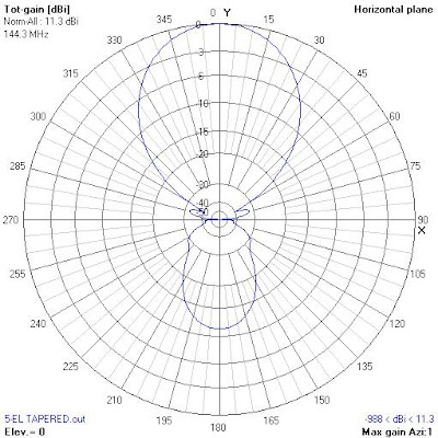
This time the fed element is a folded dipole with 0.5λ transmission line balun (68.5 cm of RG-58 coax). The length of the arms of the folded dipole can be adjusted so that optimum matching is achieved. As you can see on the picture below, the antenna impedance measurement results are rewarding:

The antenna has a relatively flat resonance around 144.250 MHz, with SWR not exceeding 1.1 at 0.5 MHz bandwidth. Unfortunately, it's very difficult to measure the radiation pattern inside the appartment. However, the received beacon signal strength is at least as good as on the previous 4-element antenna. Actual performance will be estimated later, during QSOs on 144 MHz.
| Distance from Reflector [mm] | Length [mm] | |
| Reflector | 0 | 1020 |
| Folded dipole | 326 | 990 (adjust to match) |
| Director 1 | 628 | 940 |
| Director 2 | 1143 | 910 |
| Director 3 | 1909 | 880 |
This time the fed element is a folded dipole with 0.5λ transmission line balun (68.5 cm of RG-58 coax). The length of the arms of the folded dipole can be adjusted so that optimum matching is achieved. As you can see on the picture below, the antenna impedance measurement results are rewarding:

The antenna has a relatively flat resonance around 144.250 MHz, with SWR not exceeding 1.1 at 0.5 MHz bandwidth. Unfortunately, it's very difficult to measure the radiation pattern inside the appartment. However, the received beacon signal strength is at least as good as on the previous 4-element antenna. Actual performance will be estimated later, during QSOs on 144 MHz.
08 August 2007
First 144 MHz QSOs
Tonight I spent two hours on 144 MHz and participated in UK VHF Activity Contest (every first Tuesday of a month). My 4-element yagi was placed next to the balcony windows, inside the appartment, resting on two wooden chairs. Yes, a very professional setup. I regret not having taken a picture :-)
The yagi was beaming 270 degrees, which I thought should cover the bearings range to England given the antenna beamwidth of about 60 degrees.
I heard some stations on 144 MHz eventually, and that was already fun. But to my amazement, I also managed to log three QSOs:
G4DEZ JO03AE SSB (310 km)
G7RAU IO90IR CW (416 km)
M0BRA IO91PK SSB (351 km)

I also heard a few stations from the Netherlands (PD2KMD, PA0ADG, PA4PS), one from France (JO10GK - maybe F2YT?) and several other stations from England - G0VJG/p, G3SDC/A, G3CWI/p. Propagation conditions were interesting, with QSB and sometimes a very fast fading. Signals were usually at or below sensitivity threshold and I could really make good use of the DSP receiver features. The QSO with G7RAU was very enjoyable and I felt as if I was just having a contact with my first DX like 15 years ago.
I realize I could probably work more stations from the roof of my building with just a dipole, but having 3 QSOs from an indoor antenna on the first floor was a thrill!
The yagi was beaming 270 degrees, which I thought should cover the bearings range to England given the antenna beamwidth of about 60 degrees.
I heard some stations on 144 MHz eventually, and that was already fun. But to my amazement, I also managed to log three QSOs:
G4DEZ JO03AE SSB (310 km)
G7RAU IO90IR CW (416 km)
M0BRA IO91PK SSB (351 km)

I also heard a few stations from the Netherlands (PD2KMD, PA0ADG, PA4PS), one from France (JO10GK - maybe F2YT?) and several other stations from England - G0VJG/p, G3SDC/A, G3CWI/p. Propagation conditions were interesting, with QSB and sometimes a very fast fading. Signals were usually at or below sensitivity threshold and I could really make good use of the DSP receiver features. The QSO with G7RAU was very enjoyable and I felt as if I was just having a contact with my first DX like 15 years ago.
I realize I could probably work more stations from the roof of my building with just a dipole, but having 3 QSOs from an indoor antenna on the first floor was a thrill!
07 August 2007
Balcony railing impedance measurement
I have measured the impedance of my balcony railing. It's really bad :-)
To be precise, what has been measured is impedance of the railing transformed by the RG-58 feedline (about 5 metres long). I'll attempt to measure the antenna impedance directly later.
These are the values as seen by the antenna tuner output:
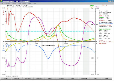
The scan covers 2-32 MHz range. Three resonant frequencies can be seen (9.3, 19.4 and 27.6 MHz), with the best impedance match around 16 MHz.
At 9.3 MHz the impedance is very low - about 6 ohms.
At 19.4 MHz it reaches about 240 ohms.
At 27.6 MHz it's close to 10 ohms again.
In my opinion the first resonance is the one I suspected to be between 7 and 10 MHz, related to a 0.25λ longitudinal dimension of the railing.
Second resonanse is that of an end-fed 0.5λ element.
Third resonance coresponds to 1.5λ case.
Impedance values at amateur bands are not encouraging, with SWR well above 3.
Somehow the antenna tuner is able to match the railing and the SWR meter in the radio displays values close to 1.
There's not much I can do at this point. I might add inductance below 9.3 and above 19.4 MHz as well as capacitance between 9.3 and 19.4 MHz in series with the fed element to bring the imaginary part of impedance to zero.
To be precise, what has been measured is impedance of the railing transformed by the RG-58 feedline (about 5 metres long). I'll attempt to measure the antenna impedance directly later.
These are the values as seen by the antenna tuner output:
The scan covers 2-32 MHz range. Three resonant frequencies can be seen (9.3, 19.4 and 27.6 MHz), with the best impedance match around 16 MHz.
At 9.3 MHz the impedance is very low - about 6 ohms.
At 19.4 MHz it reaches about 240 ohms.
At 27.6 MHz it's close to 10 ohms again.
In my opinion the first resonance is the one I suspected to be between 7 and 10 MHz, related to a 0.25λ longitudinal dimension of the railing.
Second resonanse is that of an end-fed 0.5λ element.
Third resonance coresponds to 1.5λ case.
Impedance values at amateur bands are not encouraging, with SWR well above 3.
Somehow the antenna tuner is able to match the railing and the SWR meter in the radio displays values close to 1.
There's not much I can do at this point. I might add inductance below 9.3 and above 19.4 MHz as well as capacitance between 9.3 and 19.4 MHz in series with the fed element to bring the imaginary part of impedance to zero.
03 August 2007
First 2m yagi experiment
I have designed a simple 4-element yagi with 4nec2 today to have a basic antenna for 2 meters indoors operation and as a starting point for future 2m antenna experiments.
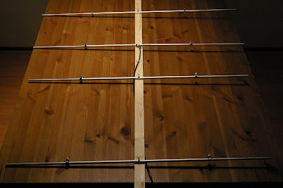
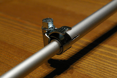
The antenna elements are aluminium tubes of 8 and 10 mm diameter. Thicker sections are attached to a wooden boom with steel screws. The thinner tubes slide in and out as necessary to provide different total element lengths (fixed with hose clamps).
4nec2 indicated that for 10 mm elements the antenna will have an impedance of 49 ohm (purely resistive) at 144.2 MHz. While making the antenna I kept the original elements size, even though 50% length is now 8 instead of 10 mm diameter and the hose clamps have their capacitance. The antenna was located in the living room and fed with about 10 meters of RG-58 (approximately 1.8 dB loss). The first impedance measurement revealed a resonance at 144.8 MHz and about 40 ohms impedance.
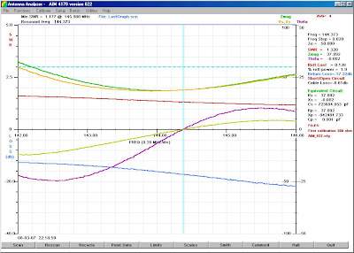
I have rerun 4nec2, this time with true element diameters. The general conclusion of the analysis was that the elements had to be extended by about 10 mm. After I applied length corrections to all elements, the impedance curves look like this:
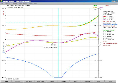
There is a resonance at 144.4 MHz, but the impedance at this region is about 40 ohms.
The best match is offered just above 146 MHz, with resistance of about 50 ohms and reactance very close to zero. I will have to make the fed element a bit longer to see if I can get the best match region down by 2 MHz or so.
The antenna elements are aluminium tubes of 8 and 10 mm diameter. Thicker sections are attached to a wooden boom with steel screws. The thinner tubes slide in and out as necessary to provide different total element lengths (fixed with hose clamps).
4nec2 indicated that for 10 mm elements the antenna will have an impedance of 49 ohm (purely resistive) at 144.2 MHz. While making the antenna I kept the original elements size, even though 50% length is now 8 instead of 10 mm diameter and the hose clamps have their capacitance. The antenna was located in the living room and fed with about 10 meters of RG-58 (approximately 1.8 dB loss). The first impedance measurement revealed a resonance at 144.8 MHz and about 40 ohms impedance.
After extending the fed element by 1 cm (5 mm on each side) the resonance frequency came down to almost 144.3 MHz:
I have rerun 4nec2, this time with true element diameters. The general conclusion of the analysis was that the elements had to be extended by about 10 mm. After I applied length corrections to all elements, the impedance curves look like this:
There is a resonance at 144.4 MHz, but the impedance at this region is about 40 ohms.
The best match is offered just above 146 MHz, with resistance of about 50 ohms and reactance very close to zero. I will have to make the fed element a bit longer to see if I can get the best match region down by 2 MHz or so.
02 August 2007
My HF antenna
Antenna is definitely an overstatement in this case.
There is no chance to place any piece of wire outside the building, so I'm left with little choice on HF. I could build a small indoor antenna or try to use what's already available.
My operating hours fall at late evening or at night, so my preference is to use 3.5, 7 and 10 MHz bands. Anything that fits indoors and can be quickly assembled/disassembled would be rather inefficient at these frequencies. But what about the balcony with a 10-meter railing made of aluminium?
The picture below shows a model of the balcony railing. Imagine it's on the first floor, with one balcony below and several above and next to it. To the right there is a massive steel structure which extends horizontally and vertically along the exterior of the building. Amazingly, my balcony is the only one which is not directly connected with this structure.
There is no chance to place any piece of wire outside the building, so I'm left with little choice on HF. I could build a small indoor antenna or try to use what's already available.
My operating hours fall at late evening or at night, so my preference is to use 3.5, 7 and 10 MHz bands. Anything that fits indoors and can be quickly assembled/disassembled would be rather inefficient at these frequencies. But what about the balcony with a 10-meter railing made of aluminium?
The picture below shows a model of the balcony railing. Imagine it's on the first floor, with one balcony below and several above and next to it. To the right there is a massive steel structure which extends horizontally and vertically along the exterior of the building. Amazingly, my balcony is the only one which is not directly connected with this structure.

The railing is fed at the bottom right of the picture with RG-58 cable. The coax shield is connected to the metal structure. I use crocodile clips to attach the feedline to this bizzare antenna only when it is about to be used.
I realize this antenna is not very efficient, its radiaton pattern is random, there's a lot of losses in the surrounding metal objects and in the ground, etc. I am really surprised that the built-in antenna "tuner" (or matching circuit, to be correct) in my transceiver does actually match the antenna impedance on all HF bands with SWR values below 1.2! I suppose this piece of railing might be a wideband radiator (it's quite different from a copper wireline) with resonance on 7 or 10 MHz, where it is about a quarter wavelength.
Another challenge is the amount of interference I notice on all bands. It starts below 1 MHz and extends well above 30 MHz, with local peaks and minima. 10 MHz is mostly quiet, but 3.5, 7, 14, 18 and 21 MHz are full of S9 noise (at 3 kHz IF bandwidth). Using a narrowband filter (I use 250 or 500 Hz on CW) helps reduce the interference a bit, but even then it's only possible to copy only strong stations.
The noise is definitely radiated by AC power lines inside the building. I suspect it's one of the "Ethernet over AC line" systems, probably dLAN by Devolo, recently selected by the national Dutch telephone company.
Subscribe to:
Posts (Atom)

