To be precise, what has been measured is impedance of the railing transformed by the RG-58 feedline (about 5 metres long). I'll attempt to measure the antenna impedance directly later.
These are the values as seen by the antenna tuner output:
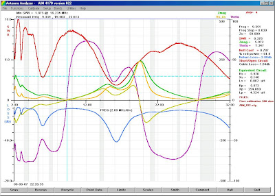
The scan covers 2-32 MHz range. Three resonant frequencies can be seen (9.3, 19.4 and 27.6 MHz), with the best impedance match around 16 MHz.
At 9.3 MHz the impedance is very low - about 6 ohms.
At 19.4 MHz it reaches about 240 ohms.
At 27.6 MHz it's close to 10 ohms again.
In my opinion the first resonance is the one I suspected to be between 7 and 10 MHz, related to a 0.25λ longitudinal dimension of the railing.
Second resonanse is that of an end-fed 0.5λ element.
Third resonance coresponds to 1.5λ case.
Impedance values at amateur bands are not encouraging, with SWR well above 3.
Somehow the antenna tuner is able to match the railing and the SWR meter in the radio displays values close to 1.
There's not much I can do at this point. I might add inductance below 9.3 and above 19.4 MHz as well as capacitance between 9.3 and 19.4 MHz in series with the fed element to bring the imaginary part of impedance to zero.
No comments:
Post a Comment